Reactive power compensation
Technical and economic feasibility
Electrical energy is produced, transmitted, distributed, and consumed mainly as alternating current. Alternating current, in contrast with direct current, features both active resistance, and inductive and capacitive resistance (reactive power)A feasibility study of reactive power compensation in 10 (6) –0.4 kV electrical distribution networks has practical applications for electric grid companies for optimizing operating modes depending on the specific loads and parameters of electrical distribution networks.
Valery Ovseichuk, Doctor of Economics, Professor
Herman Trofimov, Doctor of Technical Sciences, Professor
Alexander Katz, Ph.D. in Technical Sciences, Associate Professor
Joseph Wiener, Ph.D. in Technical Sciences
Rustam Ukasov, Engineer
Andrey Shimko, Economist
Moscow, Almaty
Without exception, all AC power consumers are consumers of reactive power (RP) too. RP consumers are electric power devices which use an alternating magnetic field - e.g. asynchronous motors, induction furnaces, welding transformers, rectifiers, etc. - as well as power supply equipment - e.g. transformers, power lines, reactors, and other equipment.
According to estimates [1], approximately 60% of all reactive power associated with the formation of alternating magnetic fields is consumed by asynchronous motors and approximately 25% by transformers.
The consumption of active power (AP) and reactive power (RP) is always accompanied by losses. AP and RP are lost in the elements and electrical equipment of the electric network (in overhead and cable lines, power transformers, reactors, step-down substations, and other equipment).
We should note a significant difference in the ratio of consumption and losses of AP and RP. The majority of AP is efficiently used by electrical devices and only a small amount (approximately 10%) is lost in network elements. RP in network elements and electrical equipment is usually commensurate in magnitude with the active power consumed by power receivers.
AP is produced only by generators. RP is produced by generators (synchronous motors in an over-excitation mode) and other sources: capacity of overhead and cable lines, synchronous compensators, and capacitor banks.
The transfer of RP from power plant generators over an electric network to consumers results in AP losses in the network and, additionally, puts loads on the elements of the electric network, reducing overall throughput. As a rule, an increase in the output of RP by station generators in order to deliver it to consumers is impractical; the greatest economic effect is achieved when compensating devices are placed close to the devices that consume RP [2].
When developing capacity balances in the electric network, the balance of the AP and the RP network must be drawn up so that their consumption, including losses in the network, is compensated for by the generation of AP and RP at the power plant, by means of transmission from neighboring power systems, and/or by means of other sources of PM. In this case, reserve power is necessary in cases of emergency or repair operations.
When assessing the consumed RP, the power factor cos φ = P / S is used, where P, S are the values of active and apparent power, respectively.
Power factor alone is an incomplete description of consumed reactive power since, at values of cos φ close to unity, the consumed RP is still quite large.
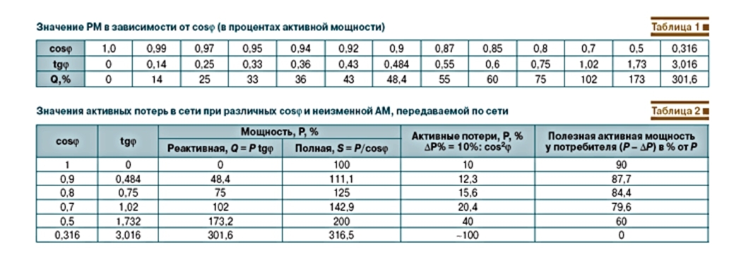
For example, with a high value of cos φ = 0.95, the RP consumed by the load is 33% of the consumed AP (Table 1). When cos φ = 0.7, the amount of consumed RP is almost equal to the value of AP.
A more realistic and practical description of RP consumption is the RP coefficient tg φ = Q / P, where Q, P are the values of RP and AP, respectively. The transmission of RP to the consumer and its consumption in the network leads to additional AP losses in the electrical distribution network. Table 2 describes useful, consumable AP when transmitting an unchanged AP (P = 100%) over a network for various cos φ and under the condition that, when transmitting this amount of power, the AP losses in the network with cos φ = 1 are equal to DP = 10%. AP losses in the electric network:
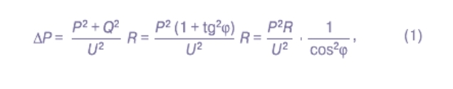
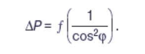
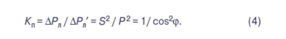
From equation (1) it follows that, at constant parameters of transmitted power (P), voltage (U), and network resistance (R), the amount of AP losses in the network is inversely proportional to the square of the power factor of the transmitted load, or
Economic evaluation of the effectiveness of increasing cos φ
We will consider the economic significance of active electricity losses during transmission and consumption of RP using the example of 10 (6) –0.4 kV networks of regional grid companies (RGC) RAO “EES Russia”. Let us take the most typical, average-weighted cos j = 0.85 in 10 (6) –0.4 kV RGC electrical distribution networks [3, 4]. According to [8], the supply of electricity to the RGC network of RAO “EES Russia” in 2007 amounted to 742.5 billion kWh. Of this amount of electricity, approximately 50%, or 370 billion kWh, was supplied through 10 (6) –0.4 kV networks. Electricity losses in the RGC 10 (6) –0.4 kV networks, according to 2007 estimates, amounted to 11.6%:

Appropriate compensation of RP in electrical distribution networks
Due attention has not been paid to the problems of compensation of RP (CRP) in 10 (6) –0.4 kV electrical distribution networks Domestic load depends on the characteristics of domestic electrical devices (incandescent lamps, electric stoves, electric heaters, etc.) [3]. The nature of used domestic load has changed dramatically with the introduction of new consumers devices (microwave ovens, air conditioners, freezers, fluorescent lamps, washing machines and dishwashers, personal computers, etc.). These devices consume significant RP and AP. In 1987, the Ministry of Energy and Electrification of the USSR [9] established a CRP of cos φ = 0.858 (tg φ = 0.6). However, according to various expert estimates, the power factor in electrical distribution networks is approximately 0.8–0.85 (tg φ = 0.75–0.62). In 2007, Russian Federation [10] requirements for the minimum value of the RP coefficient for consumer connections to the 10 (6) –0.4 kV network were significantly tightened, and cos φ = 0.944 (tg φ = 0.35) was installed for the 0.4 kV network and cos φ = 0.93 (tg φ = 0.4) for the 6–20 kV network.CRP can significantly improve the technical and economic performance of 10 (6) –0.4 kV electrical distribution networks through:
1) reduction of AP losses; and
2) increasing the capacity of 10 (6) / 0.4 kV step-down transformers;
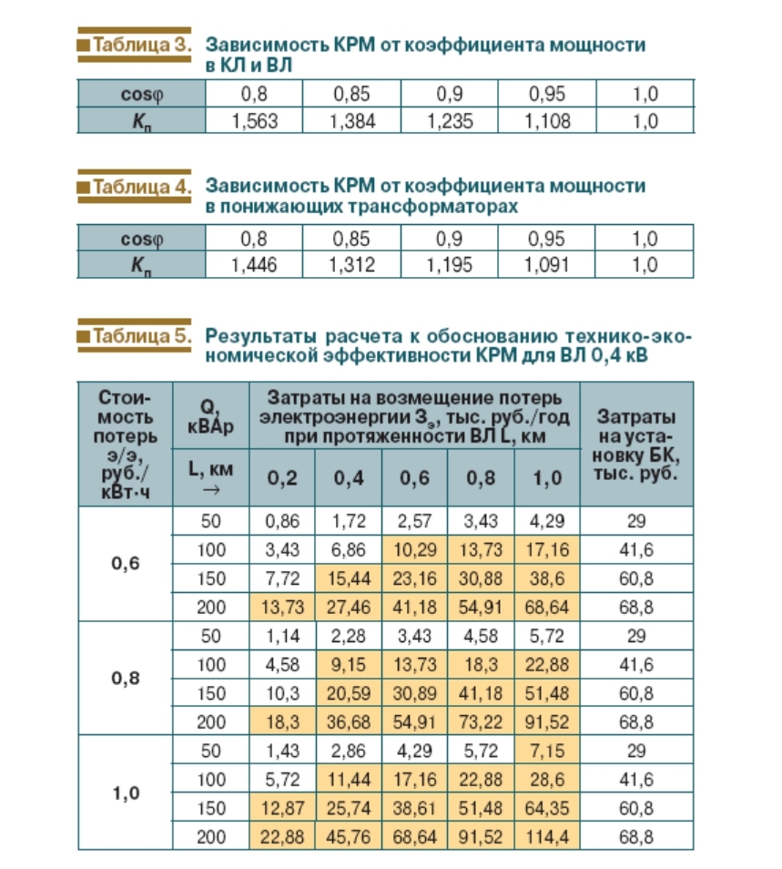
2. The values of Зэ (costs of power loss compensation) are highlighted in yellow where the payback period for the cost of production is 5 years or less.
3. Voltage loss (drop) network reduction ;
4. Possible balancing voltages in 0.38 / 0.22 kV networks with unbalanced loads.
The above factors associated with CRP in 10 (6) and 0.4 kV electrical distribution networks of are considered in detail below.
Reducing AP losses in a 10 (6) kV distribution network
To assess the degree of AP loss reduction, let us assume that N of 10 (6) / 0.4 kV (TS) transformer substations with a set rated power Sн (kVA) are powered by a radial circuit from the main substation (MS). The transformers are equally loaded with power S with a power factor cos φ. With cable (overhead) lines - at a complete CRP of 0.4 kV TS, - the AP losses in the distribution network will be equal (disregarding RP losses in 10 (6) / 0.4 kV transformers):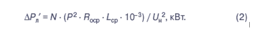

10 (6) / 0.4 kV step-down transformers
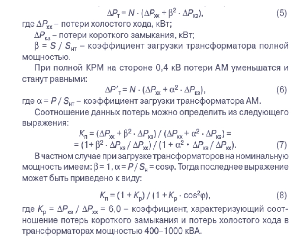
AP losses in transformers are characterized by a more complex relationship compared to power lines
Decrease in AP losses in a 0.38 kV distribution network
The main losses of electricity are accounted for by 0.4 kV distribution networks. These losses can be calculated using the expressions given above for a 6–10 kV network.In this case, the installation of a CB on the 0.4 kV buses of 10 (6) / 0.4 kV transformer substations will not lead to a significant reduction in AP losses in a 10 (6) –0.4 kV distribution network. This can be achieved only by installing the CB at the secondary 0.38 / 0.22 kV input distribution points of direct RP consumption.
The cost of compensating for electricity losses from the transmission of RP Q through a 0.4 kV network element of length L and resistivity Ro are determined by the expression:

C - the cost of electricity purchase losses by the grid company from energy sources, in rubles / kW h.
For example, Table 5 demonstrates the technical and economic efficiencies of the CRP for the 0.4 kV overhead line with the following averaged parameters: Rоср = 0.183 Ohm / km, Xоср = 0.3 Ohm / km for sections from 120 to 185 mm2. In the calculations, it was assumed that t = 2500 h, and the cost of purchasing electricity losses ranged between 0.6–1 rubles / kWh.
Calculations reveal that, with a reactive load of more than 100 kVAr and an overhead line length of more than 200 m, the return on investment (ROI) of a CB installation will be recouped within 5 years considering only cost savings achieved by AP loss reductions.
It should be noted that, according to the VDEW (Association of German Power Supply Companies), in Germany's distribution networks, due to CRP of a weighted average cos φ = 0.9, approximately 9 billion kWh of active energy was saved in 1999 alone, which amounted to more than 20% of the total (36.4 billion kW h) volume of transit losses [11].
Increasing the capacity of 10 (6) / 0.4 kV step-down transformers
The increase in power consumption (including increasing reactive power consumption, as noted above) leads to a requirement for new substations. CRP, however, offers an alternative to the construction of new TS. The value of RP, which can be passed through a transformer with its rated power Srp, is determined from the following expression: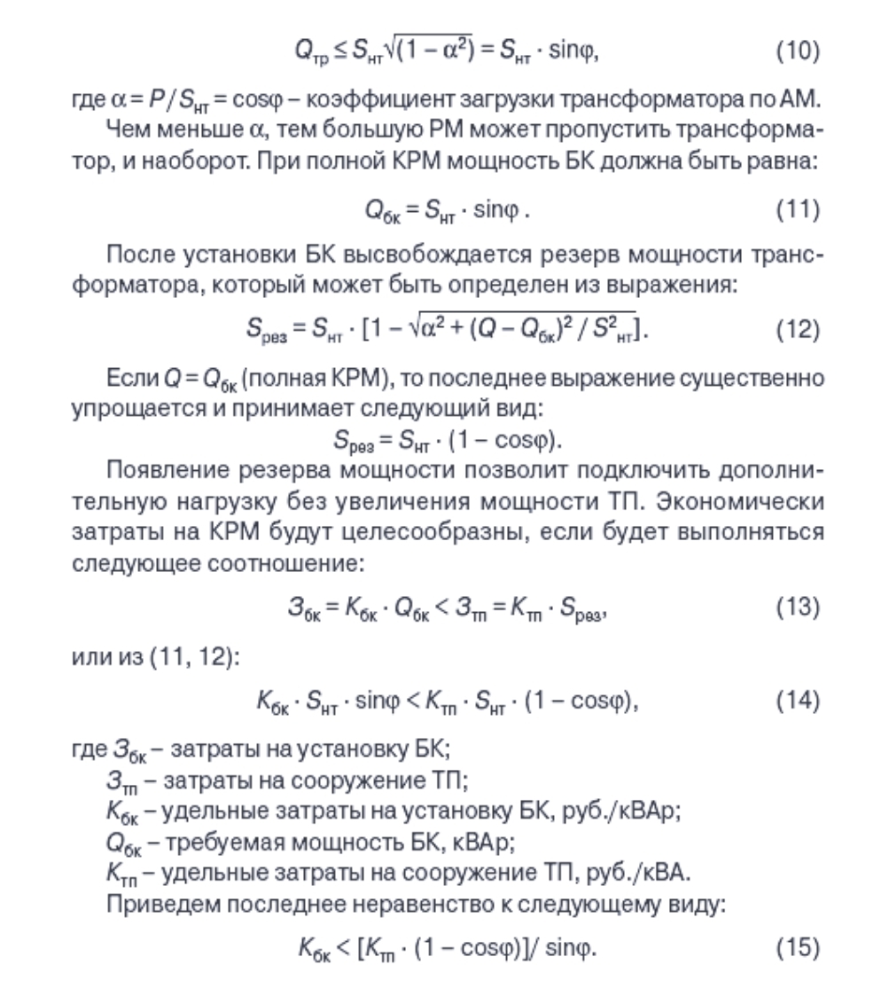
Kcb <(1333.1666) rub./kVA.
According to the data of JSC “Ust-Kamenogorsk Condenser Plant”, the unit costs for regulated CB are Kcb = (360 - 500) rubles / kVAr [12], clearly demonstrating the advantages of CB installation.
CRP is, therefore, an economical alternative to increasing the capacities of consumer electrical distribution networks.
Reducing distribution network voltage losses (drops)
Voltage losses in cable (overhead) lines
The voltage loss in cable (overhead) lines is determined by the formula:
Xоср — average specific inductance of the cable (overhead) line, Ohm / km (for overhead lines Xоср = 0.3 Ohm / km, and for cable lines Xоср = 0.06 Ohm / km [3]);
UH - the rated voltage of the distribution network, kV.
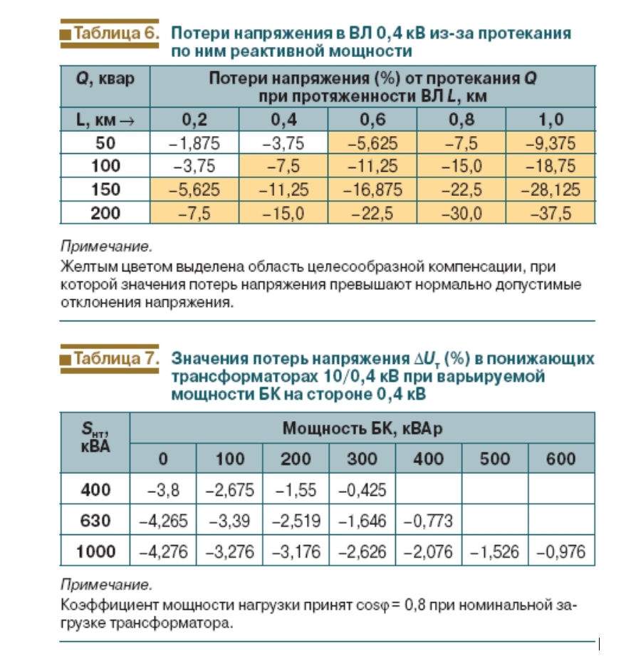
The ratio of active and inductive resistances in OHL is of a different nature and, where aluminium wires have a 120–240 mm2 diameter, the resistance ranges from 0.837–0.41. Therefore, the voltage loss in 0.4 kV OHL substantially depends on the RP (see Table 6).
At present, housing starts in Russia have increased substantially with a consequential increase in domestic, electrical demand.
Electricity is mainly supplied by OHL, and the combination of low-density property developments (e.g. cottages, cabins, and dachas) and Russia's vast territory makes the construction of new transmission / distribution networks especially costly. OHL also features a rather high percentage of voltage drop.
At maximum load in the autumn-winter period, extremely low voltage levels (up to 160–170 V) are observed at inputs to residential premises in certain regions; the electrical use among consumers is 2–3 times higher than the GOST 13109-97 parameters. The network cannot meet consumer demand, and the system often fails. Many individual consumers have therefore purchased and installed voltage stabilizers to increase their available power. However, voltage stabilizers, being electric devices with a relatively low power efficiency contribute to an even greater increase in voltage losses.
The best solution, as previously mentioned, is the increased the installation of CB in the 0.38 / 0.22 kV distribution network.
Alternatively, many developed countries use high voltage overhead lines to supply the load, which is transmitted over a large area. Low-power step-down pole transformers then distribute power to domestic consumers.
Voltage losses in 19 (6) /0.4 kV step-down transformers
Voltage losses in 10 (6) / 0.4 kV step-down transformers are determined from the formula:
XT is the inductive resistance of the transformer, Ohm;
UH is the rated voltage of the network to which RT and XT connected, kV;
P, Q - the active (kW) and reactive (kVAr) transformer loads, respectively.
Table 7 shows the voltage loss values DUT (%) in 10 / 0.4 kV step-down transformers with a variable power of the CB on the side of 0.4 kV.
From the data, full CRP use on the 0.4 kV side is indicated. In such a case, the voltage adjustment range due to the reduction of voltage losses in step-down transformers would increase by an average of + 3.4%.
Voltage balancing in networks with unbalanced loads
Different devices individual apartments in multi-story buildings and private housing construction has led to an increase in load asymmetry.This single-phase consumer asymmetry results in significant currents, comparable in magnitude with phase currents, flowing in the neutral wire of the 0.38 / 0.22 kV trunk cable and overhead lines of leading to additional power losses.
The inclusion of capacitors to balance the mode directly to phase voltages will reduce the zero-sequence currents to an acceptable value and provide simultaneous CRP.
For such unbalanced load networks, control schemes for single-phase CB controllers have been developed (for example, the Epcos AG type BR6000). In addition, each of the regulators independently switches the capacitance of the capacitors in the controlled phase in accordance with the value of the angle φ measured in the four quadrants of the complex plane.
Literature
1. Handbook of power consumption in industry / Ed. G.P. Minina and Yu.V. Kopytova. - M.: Energia, 1978. - 496 p.2. Pauli V.K., Vorotnikov R.A. Reactive power compensation as an effective means of rational use of electricity // Energoekspert. - 2007. - No. 2.
3. The Regulation on the calculation and justification of standards for technological losses of electricity during its transmission through electric networks / Order of the Ministry of Industry and Energy of Russia dated 04.10.2005 No. 267, reg. No. 7122 dated 28.10.2005 of the Ministry of Justice of Russia.
4. Zhelezko Y.S. Methods for calculating load losses of electricity in radial networks of 0.38–20 kV according to the generalised parameters of the circuits // Electric stations. - 2006. - No. 1.
5. Reactive power compensation. Matic-electro. - M.: 2007.
6. Solving problems of normalising reactive power flows in electrical distribution networks // Energoekspert. - 2007. - No. 2.
7. Zhelezko Y.S. New regulatory documents that define the relationship between network organizations and electricity buyers in terms of reactive power consumption. Materials of the sixth scientific and technical seminar “Rationing and reduction of electrical energy losses in electric networks - 2008” (collection of reports). - M.: Dialog-electro, 2008, S. 12–15.
8. Glushkov V.M., Gribin V.P. Reactive power compensation in electrical installations of industrial enterprises. - M.: Energy, 1975 .- 103 p.
9. Standards for the level of reactive power compensation in electric networks of ministries and departments for the period up to 2000. USSR Ministry of Energy and Electrification. - 1987.
10.The procedure for calculating the ratio of consumption of active and reactive power for individual energy receivers (groups of energy receivers) of consumers of electric energy, used to determine the obligations of the parties in agreements on the provision of services for the transfer of electric energy (energy supply agreements). Approved by order of the Ministry of Industry and Energy of Russia. dated February 22, 2007. No. 49.
11.Power Factor Correction. Power Quality Solutions. Published by Epcos AG. Edition 04/2006. Ordering No. EPC: 26017-7600. Printed in Germany. 79 p.
The price list of adjustable low voltage capacitors, multi-stage. JSC Ust-Kamenogorsk Condenser Plant, 2007.
